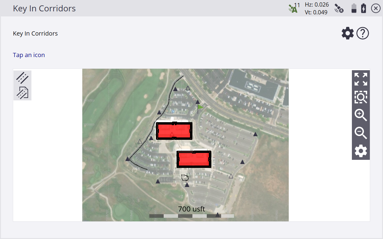
Key In Corridors
NOTE – The Roading Stakeout and Measurement module is required (see Siteworks modules). Key In Corridors is not supported on the Android operating system; it is only available on Windows 10 operating systems. In version 1.20, the name was changed from Key in Roads to Key in Corridors.
From the COGO menu, tap Key In Corridors  .
.
A variety of functions are available in the bar on the left:
|
Icon |
Description |
|---|---|
|
|
Create/edit a corridor alignment. |
|
|
Create and position corridor templates. |
|
|
Create stakeout points at a certain station and offset from the corridor alignment. |
|
|
Create stakeout points at a certain station and with a deflection angle from the corridor alignment. |
|
|
Change the key in corridor entry method. |
Creating an alignment
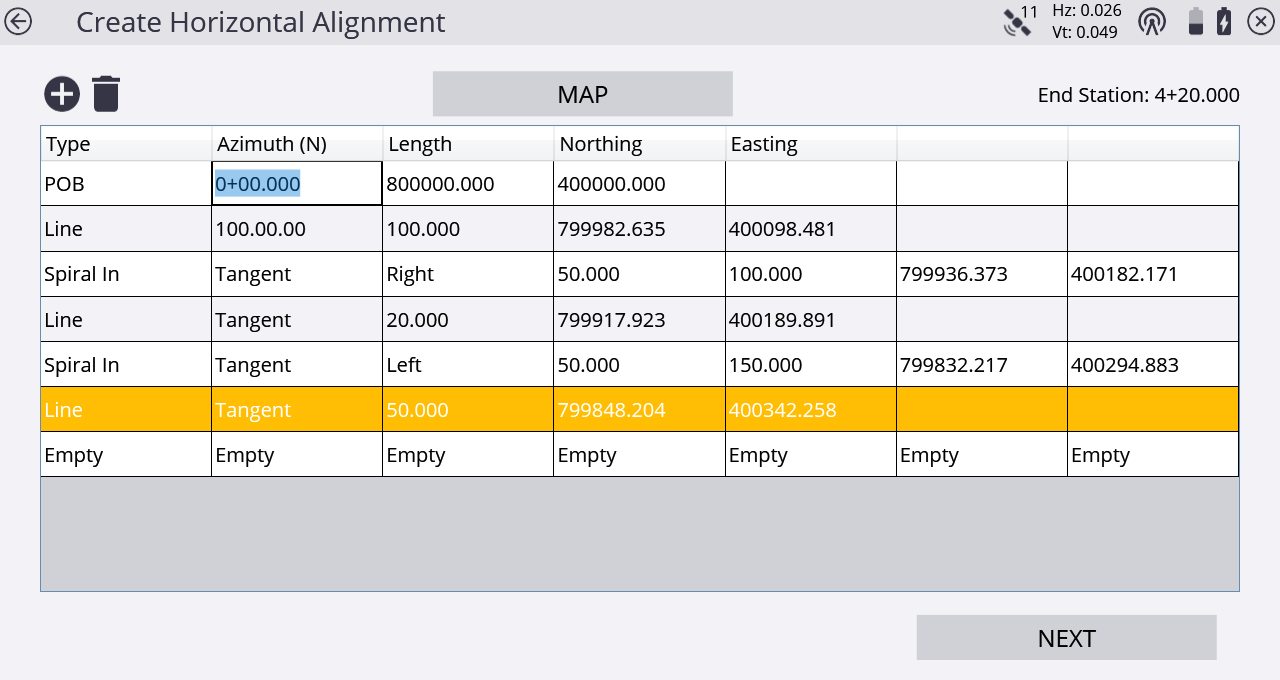
Tap the Create/Edit corridor alignment ![]() icon. A tabular entry screen appears to enter the geometry for the horizontal and optional vertical alignment.
icon. A tabular entry screen appears to enter the geometry for the horizontal and optional vertical alignment.
Complete the numeric boxes to define it.
To convert a polyline of the current loaded design or work order in an alignment, tap Map.
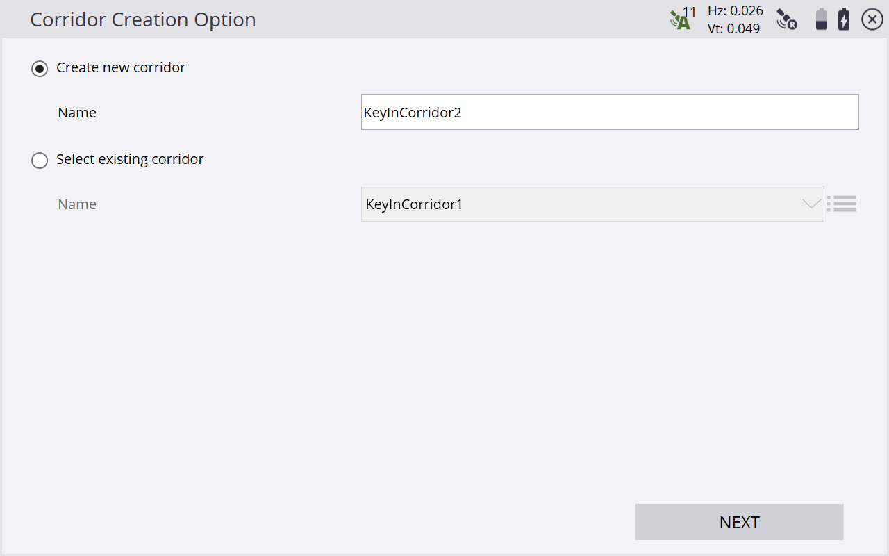
If corridors already exist in the current design that were created in the Siteworks software, you are prompted to choose to edit an existing corridor or create a new one:
The following table shows the record types that the Siteworks software supports and the data that you must enter for each type. Depending on the Key In Corridor settings, the alignment can be entered via segments or via coordinates for the points of intersections. The POB is the Point Of Beginning, which is always the first record for a horizontal alignment and contains the start station and coordinates. The azimuth is always automatically computed and appears in the table as Tangent. If you tap on this field, the software displays the actual calculated azimuth. If required, you can overwrite it with your own value. You can also enter the azimuth as a bearing (that is, S 90 W = azimuth of 270°).
|
Record type |
Col1 |
Col2 |
Col3 |
Col4 |
|---|---|---|---|---|
|
POB (Point of Beginning) |
Station |
Northing |
Easting |
|
|
Line |
Azimuth |
Length |
|
|
|
Spiral In |
Azimuth |
Direction |
Radius |
Length |
|
Arc |
Azimuth |
Direction |
Radius |
Length |
|
Spiral Out |
Azimuth |
Direction |
Radius |
Length |
|
Combining Spiral |
Azimuth |
Length |
|
|
The end station value appears as you enter the corridor details. Tap Map to see the plan view of the alignment you are creating:
Creating a vertical alignment
Tap Next. The Create Vertical Alignment screen appears:
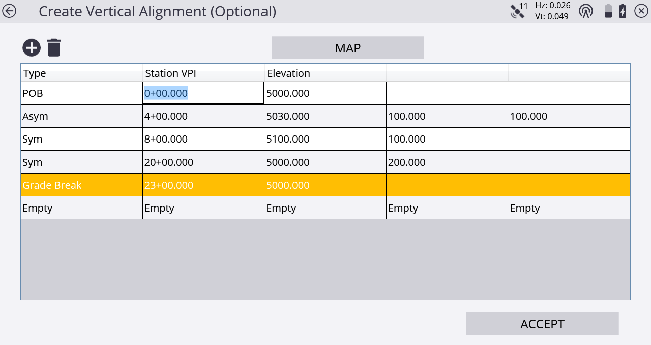
Complete the numeric boxes to define it.
This table shows the record types that the Siteworks software supports and the data that you must enter for each type. The POB is the Point Of Beginning, which is always the first record for a vertical alignment and contains the start station and elevation.
|
Record type |
Col1 |
Col2 |
Col3 |
|---|---|---|---|
|
POB (Point of Beginning) |
Station |
Elevation |
|
|
Arc VPI |
Station |
Elevation |
Radius |
|
Vertical VPI |
Station |
Elevation |
Length |
|
Grade Break |
Station |
Elevation |
|
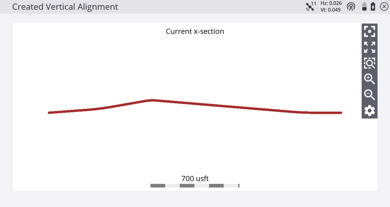
The final station value must be the same as the end station displayed in the previous Horizontal Alignment entry screen. Tap Map to see the profile view of the alignment you are creating:
If there is no current design, you are also prompted to create a new Siteworks design.
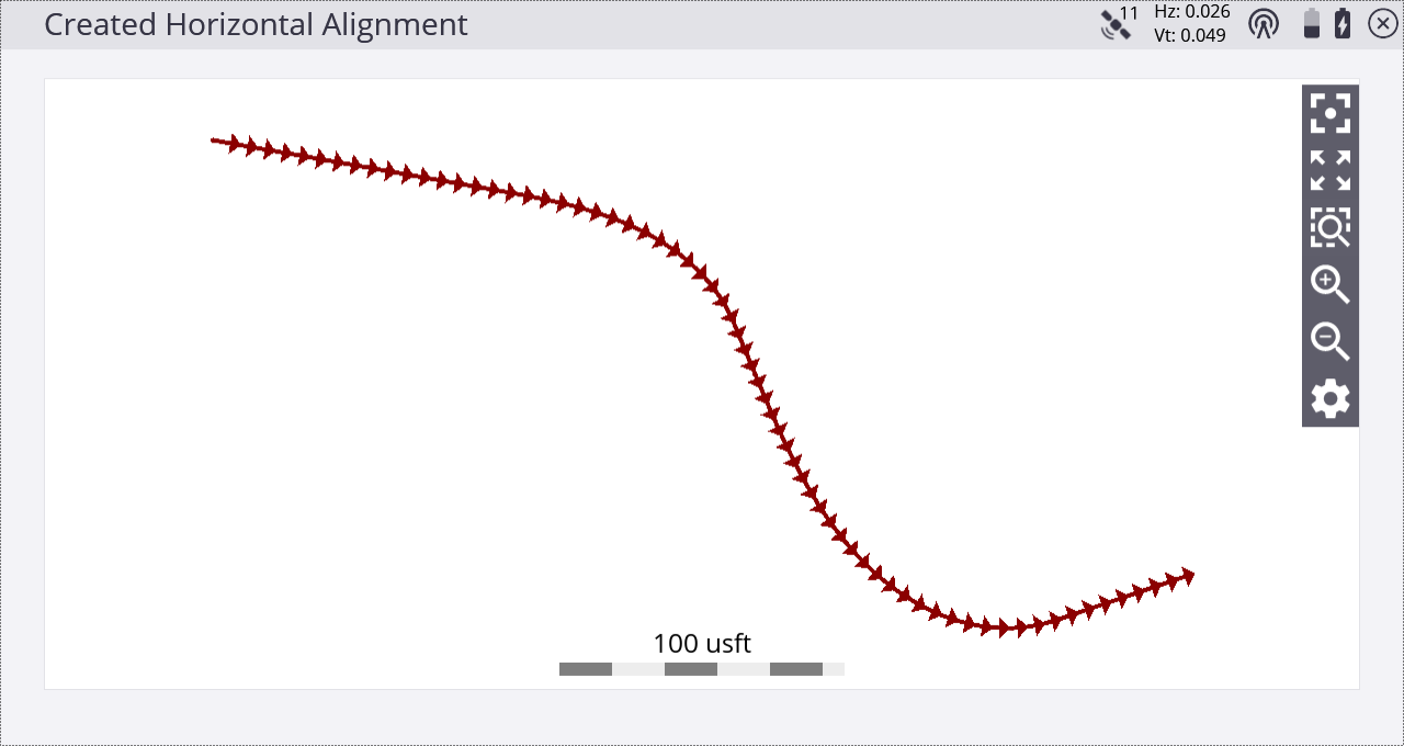
The main create corridor screen reappears showing you the plan view of the alignment you have just created:
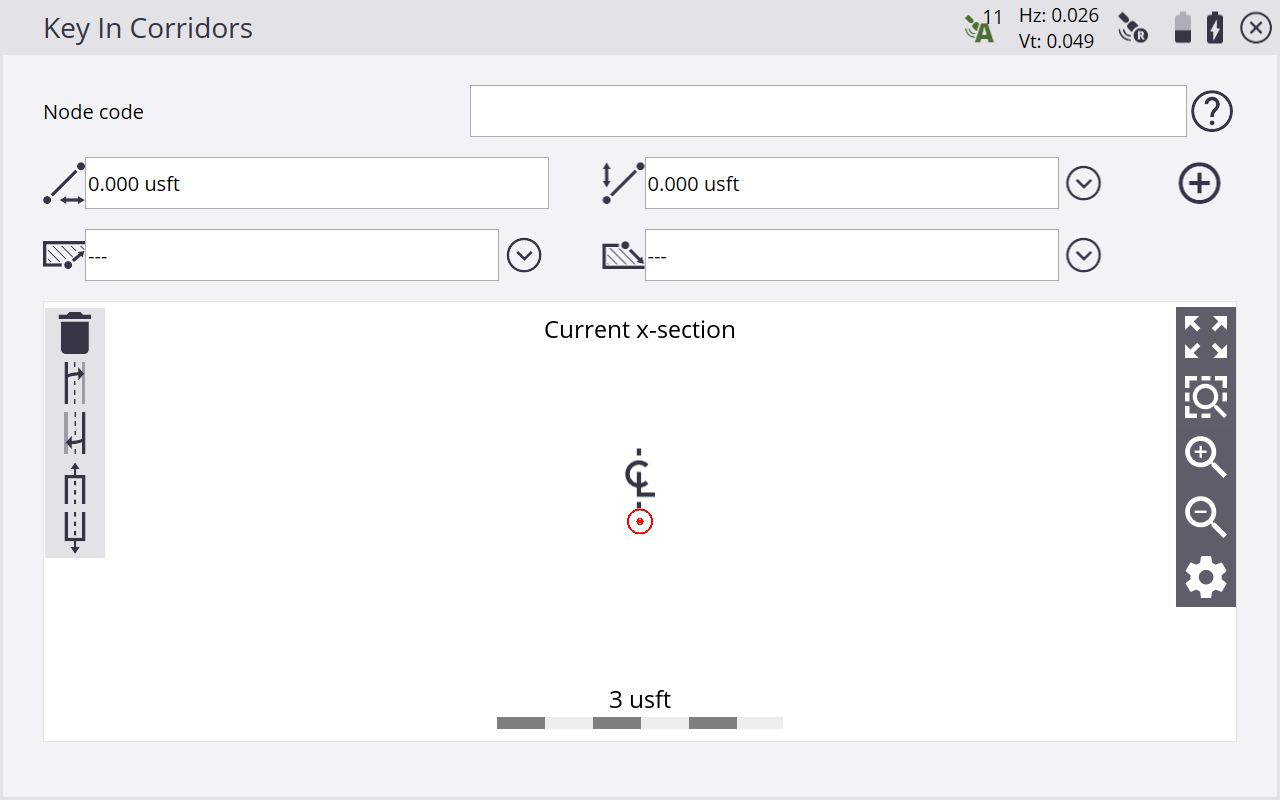
Positioning and creating templates
Tap the position and then tap the Create corridor template icon ![]() . The following screen appears:
. The following screen appears:
Pick the required station for the template.
Several functions are available in this screen:
|
Button |
Description | class
|---|---|
|
|
Code for the feature node you are about to enter. |
|
|
Horizontal distance to the last feature node which was entered. |
|
|
Vertical distance to the last feature node which was entered. |
|
|
Create Feature Node with the entered values. |
|
|
Slope values for the Cut tie. |
|
|
Slope values for the Fill tie. |
|
|
Delete feature node. |
|
|
Copy the left side to the right side. |
|
|
Copy the right side to the left side. |
|
|
Import a previously entered template. |
|
|
Export a previously entered template. |
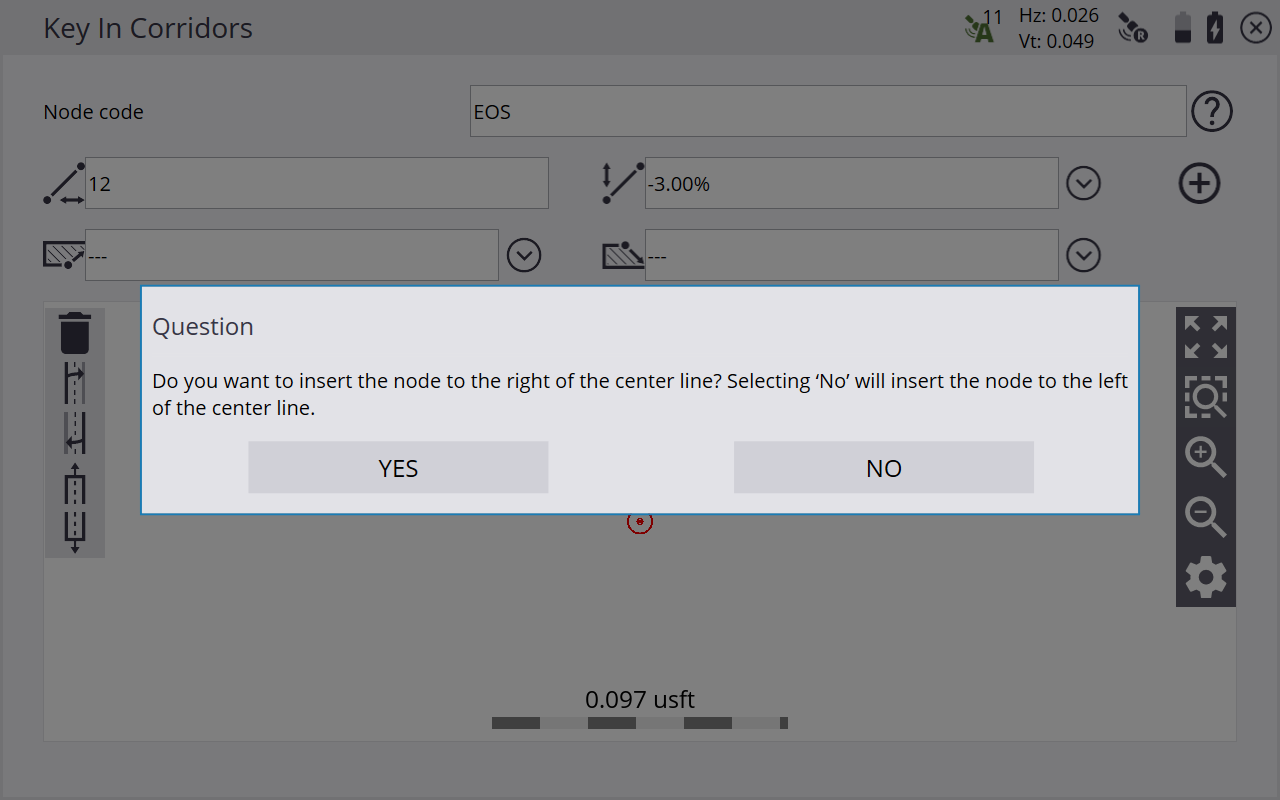
When you first enter this screen, you will be asked if the values apply for the right side or the left side of the corridor; the values are applied from the centerline.
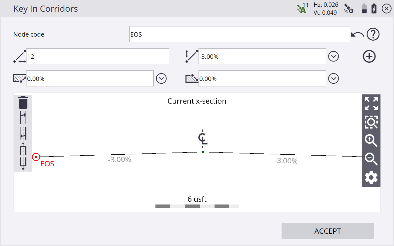
Tap Insert to see the edge of seal on the right side of the corridor on the cross section.
Copy the right side of the corridor over to the left side by tapping the copy template button. When the template is complete, tap ACCEPT. Enter a name for the template and whether you want to store the template in a library that can be accessed from any site on the controller.
Using templates means you can easily recall them by tapping the import template button. Select a template from the list. The whole definition appears in the cross section view.
You can view the templates either in plan view or cross section view at any station you want. You can also view the templates at stations between definitions. The Siteworks software transitions between the templates.
Creating stakeout points
Two COGO functions are available for creating stakeout points from a Corridor or Alignment. These are available in the Menu / COGO / Create Points/Arcs:
-
Create stakeout points at an offset from the alignment.
-
Create stakeout points at an offset from the alignment at a deflection angle. For example, this can be useful where a drain crosses a road.
These functions can be used for any corridor or alignment, not just ones created using the Siteworks software.
